
ISO 13485 7.3.4 design outputs: connect requirements to drawings, specifications and acceptance criteria
Design outputs capture the design that implements input requirements.
Follow a fictional thermometer from requirements to component and assembly specifications, acceptance criteria and verification.
Design outputs turn requirements into a defined design
The purpose of design and development outputs is to capture the concrete design that implements the input requirements.
The outputs must be usable for making the device and for verifying whether the design meets those requirements.
An appearance drawing or a photograph of a prototype rarely tells another person which components to use, how to assemble them or what constitutes an acceptable result.
This article addresses ISO 13485:2016 clause 7.3.4, Design and development outputs.
The preceding article on clause 7.3.3 dealt with the use conditions, performance and safety requirements the device must meet.
Here, the focus moves to the components, structure, behaviour and information that implement those requirements, rather than revisiting the responsibilities and stage planning covered in clause 7.3.2.
The official MDSAP Audit Approach links clause 7.3.4 to traceability between outputs and inputs and identification of outputs essential to proper device functioning.
Outputs can include product and process drawings and specifications, testing information, labelling, packaging and applicable installation or servicing information.[1] The thermometer and document arrangements below are fictional examples developed by MedQraft.
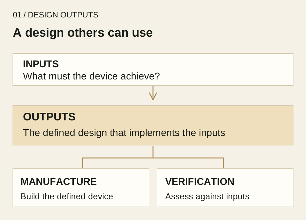
Inputs define what must be achieved; outputs describe the resulting design.
They provide manufacturing information and a defined subject for verification.
The arrows do not signify completed verification.
A fictional thermometer: an accuracy requirement needs more than a sensor name
Assume a development team has approved inputs for an electronic thermometer intended for home use.
Measurement site, operating conditions and performance criteria have already been established using evidence appropriate to that device.
This article does not supply actual accuracy limits or assembly dimensions.
The team selects a sensor and designs its mounting arrangement and signal processing.
A note saying “use a high-precision sensor” leaves purchasing unsure what to order and production unsure how to position and secure it.
Component identification and specifications, mounting and joining conditions, and the relevant circuit and software designs must agree with one another.
The performance of an individual sensor does not automatically establish the accuracy of the finished thermometer.
In this example, mounting, signal processing, calibration and use conditions may need to be considered together.
The necessary design elements depend on the measurement technology.
The practical goal is to make it possible to locate the design results that implement each input.
| Area addressed by an input | Examples of concrete design outputs | Information used in subsequent work |
|---|---|---|
| Measurement performance under defined conditions | Selected sensor specification, relevant circuit and processing design, assembly drawing | Components to purchase, structure to build and configuration to assess |
| Recognition that measurement is complete | Display design, state definitions and relevant software specification | Display and transitions to implement, expected behaviour |
| Prevention of confusion between invalid and valid results | Error handling and display design selected through risk analysis | Behaviour and assessment criteria for the relevant error conditions |
| Information needed during use | Controlled labelling and instructions-for-use content | Information to supply with the device and packaging |
This table illustrates relationships rather than a complete device specification.
Phrases such as “defined conditions” and “selected sensor” would need to resolve to approved values and precise component or document identifiers in actual records.
Organize outputs around the work someone else must perform
It is useful to assess the outputs from the recipient's perspective rather than count documents.
The following arrangement is a MedQraft practice suggestion, not a requirement for identical document names or separate files for every device.
Purchasing needs a resolved component definition.
An internal nickname in a bill of materials or unclear substitution rules can lead to a component the designer did not intend.
Link the bill of materials to the appropriate specification and control any permitted alternatives and their conditions of use.
Production needs a reproducible structure and the relevant conditions.
A picture showing a sensor's approximate location leaves room for different assembly decisions.
Define the necessary dimensions, tolerances, materials and joining conditions in the relevant drawings or instructions according to the product.
These are examples of information to consider, not a universal list for every device.
Inspection needs a defined characteristic and acceptance criteria.
“Check accuracy” does not establish the conditions or acceptable range.
Include the relevant criteria or a precise reference to them, and connect them to the applicable configuration and revision.
A value remembered by the designer is not a usable inspection reference.
Devices that require servicing also need appropriate service information.
Permitted inspection or replacement activities and associated checks should agree with the design.
A repair procedure should not be invented for a fictional device whose service model has not been defined.
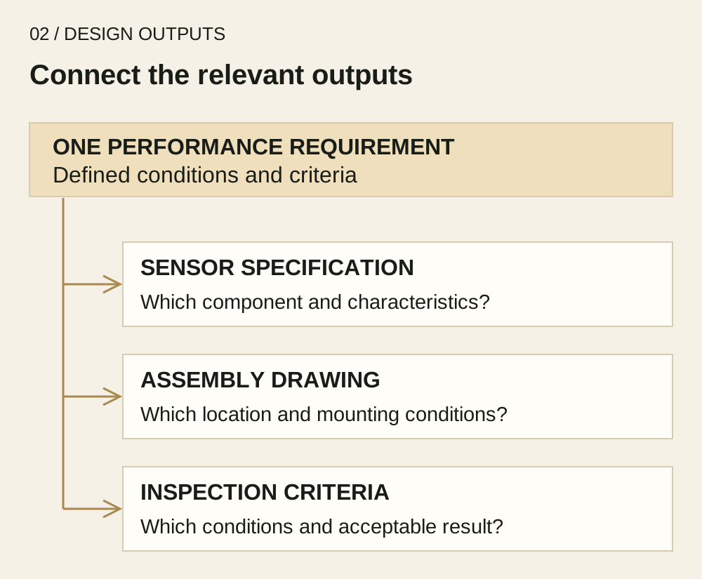
One input can connect to several outputs.
A sensor specification alone neither implements nor proves every aspect of the finished device's performance.
Defining a criterion is different from obtaining verification evidence
Linking conditions and acceptance criteria to the design outputs makes the intended assessment clear.
It does not produce a test result.
Having a criterion and demonstrating that the criterion has been met are different states.
For the fictional inspection document, an output review can establish whether the applicable configuration, conditions, method and acceptance criteria are identifiable.
Actual measurement or analysis, followed by comparison with those criteria, is needed to support a conclusion.
Design verification and routine production inspection can differ in purpose, test articles, sampling and methods; one inspection sheet should not be assumed to complete every assessment.
MDSAP describes design verification as obtaining objective evidence that outputs meet inputs.[1] Output preparation under clause 7.3.4 connects to verification under clause 7.3.6, but they are not the same activity.
Documenting the design also does not by itself complete validation for intended use or transfer to production.
Keep safety-relevant characteristics connected across documents
Suppose the fictional team's risk analysis identifies a need to distinguish a particular error state from a valid measurement.
A picture of the error screen is not enough on its own.
The relevant design must specify the conditions that trigger the behaviour and the associated display and response.
The assessment criteria must also address that state.
This is not a recommendation for a particular error-detection technique.
It illustrates how a selected risk control should continue into the actual design and assessment activities.
An organization may identify important characteristics with symbols or linked documents.
What matters is that their significance remains visible during changes, purchasing, manufacture and inspection.
Follow one requirement through the outputs before release
The following review questions are an original practice aid, to be used with the organization's review and approval procedures.
They are not a prescribed ISO form.
| Connection to review | Question |
|---|---|
| Input to output | Can the drawing, specification or behaviour definition implementing this requirement be located? |
| Output to manufacture | Are components, structure and applicable conditions specific and mutually consistent? |
| Output to acceptance decision | Are criteria included or referenced precisely? |
| Risk control to design characteristic | Are characteristics important to safety and proper use reflected in the design? |
| Review to release | Have open issues and document discrepancies been addressed and the applicable outputs approved? |
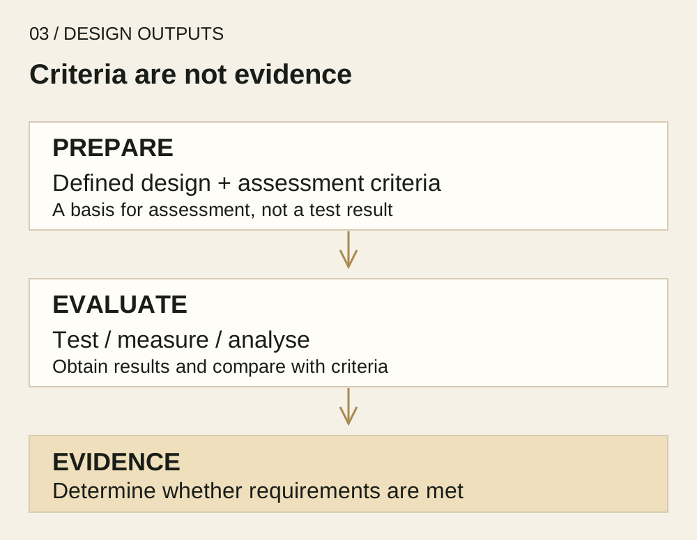
A defined design and criteria prepare the assessment.
Actual evaluation results and comparison with those criteria are needed to determine whether requirements have been met.
If a drawing and bill of materials use incompatible revisions or a reference to inspection criteria is broken, do not leave the recipient to resolve the ambiguity.
Reconcile the information and release the approved outputs.
Later design changes require consideration of the affected outputs and assessment activities as well.
Sources and scope
- MDSAP Audit Approach, MDSAP AU P0002.011, revision dated 3 August 2026.
Chapter 5 Task 7 discusses outputs and verification; Task 13 addresses design transfer.
Official document page. - Official ISO 13485:2016 publication information.
The third edition, published in 2016, is identified as current following confirmation in 2025.
Checked on 29 October 2026.
This is an original explanation based on public official sources, not the complete standard or an official translation.
Tables, diagrams and the thermometer scenario are MedQraft practice illustrations.
Actual component selection, inspection conditions, limits and applicable requirements need device-specific evidence.
Related articles
- 7.3.3 design inputs: define use, performance and safety requirements
- 7.3.2 design planning: stage responsibilities and decision criteria
- 7.1 planning of product realization
- QMS topics and the ISO 13485 clause guide
Continue through ISO 13485 clauses
Let's talk
Apply what you have read
to your product.
Tell us your product's current stage and the questions you need to review.
Discuss your questions ↗