
Move the work, change the capture: source position and local exhaust hoods
Why moving the source can change capture, even with the same hood running.
A fictional A/B layout explains capture zones and work-position review.
A local exhaust hood does not draw in dust equally from every point around it.
Moving work farther from the hood changes the airflow where emissions would arise.
A layout change made for comfort therefore also needs a review of source position.[1]
This article addresses external capturing hoods in material preparation and sample-processing areas.
It is a technical explanation for medical-device development and manufacturing teams, not an operating procedure for an enclosing laboratory fume hood.[2]
One hood, two proposed positions
Consider a fictional layout review before processing begins.
A is the original sample-tray position near the hood.
B is a proposed position farther away, intended to make hand movements more comfortable.
The hood and fan setting are assumed unchanged.
A and B represent successive positions of the same sample, not two simultaneous sources.
The change affects more than arm reach.
It also moves the location where dust would be generated.
A useful drawing therefore identifies the emission point relative to the hood opening, rather than merely showing the overall workbench.
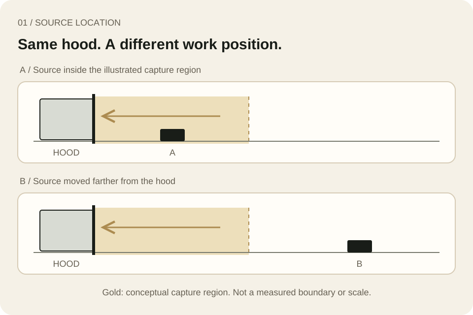
A fictional comparison with only the work position changed.
Gold indicates a conceptual capture region, not a measured boundary, scale or safe distance.
| Layout item | Review question |
|---|---|
| Sample position | Where would the contaminant actually be generated? |
| Hand and sample movement | How far would that source travel during the task? |
| Position relative to the hood | Is the entire working zone within the established capture zone? |
| Operator posture | Could the contaminant travel through the breathing zone? |
This is an original review aid, not a performance acceptance checklist.
Running is not the same as capturing
For an external capturing hood, airflow falls rapidly with distance from its opening.
HSE describes the capture zone as the region where airflow is sufficient to capture the contaminant.
The whole emission-generating working zone needs to be within that region.[1]
The gold area in the diagram is not a universal template.
Its real shape and extent depend on the system and conditions.
Do not transfer the illustration directly to a workstation marking or assign the same distance limit to every installation.
HSE also explains that feeling airflow by hand is not an effective way to judge inlet velocity.
Appropriate indicators or measurements need to be selected and interpreted for the particular system.[3] A fan-on observation alone does not establish capture at the proposed work position.
Follow the activity, not just its starting point
A sample can begin near the hood and move away as it is turned or repositioned.
Where the working zone moves, HSE discusses adjustable hoods or workstations and alternative control arrangements if suitable positioning cannot be maintained.[1]
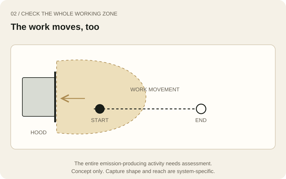
A suitable starting point does not describe the whole task.
The dashed line represents sample movement, not airflow or measured performance.
In the fictional review, the team can mark the intended movement from one end of the sample to the other before processing begins.
A still photograph showing the starting position would omit the end of that movement.
A competent person should determine how performance will be checked under representative conditions, considering the material and exposure risks.
Include surrounding air and the operator
CCOHS identifies surrounding air movement as a factor affecting capture.
Supply air, local cooling or heating, and operator movement can all matter.
It also advises locating the hood so the operator is not between the contaminant source and the hood.[2]
The practical review therefore asks about direction as well as distance.
In the fictional case, moving the tray may also change where the operator leans.
Moving it closer cannot, by itself, demonstrate effective exposure control.
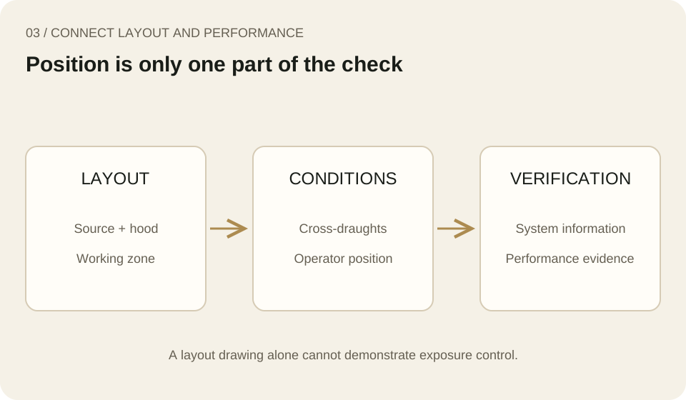
An original framework connecting layout review with performance evidence.
The drawing itself does not demonstrate exposure control.
Record the decision clearly
The following is MedQraft's practical suggestion.
It can be incorporated into an existing change or equipment record rather than creating a mandatory new form.
| Record item | Fictional entry |
|---|---|
| Reason for change | Reduce reaching by repositioning the sample tray |
| Before and after | Mark A, B and the intended working path relative to the hood |
| Other changed conditions | Note posture, nearby supply air and surrounding objects |
| Evidence used | Identify equipment information, previous checks and the scope of additional verification |
| Next decision | Agree whether to confirm the layout, review further or adjust the equipment |
The purpose is to replace “the hood is running” with a specific question: does it capture adequately at the changed work location? Where performance is uncertain, resolve the necessary equipment and specialist review before starting the task.
Verification methods and operating limits remain dependent on the material, process and system.
Related reading
- Workplace lighting and reflected glare: another example of how layout changes the conditions of a task.
- Controls to consider before personal protective equipment: the broader framework for reducing workplace risks.
Sources and scope
- HSE, HSG258: Controlling airborne contaminants at work, third edition, 2017, capturing-hood sections 142–149 and Table 10.
- CCOHS, Industrial Ventilation: Hoods, hood types, capture velocity and design principles.
- HSE, LEV Frequently asked questions, airflow checks and indicators.
Checked October 24, 2026.
These UK and Canadian technical sources support the principles discussed.
Their legal duties or inspection intervals are not presented as Korean requirements.
Applicable local law and workplace conditions require separate review.
No universal safe distance, velocity or acceptance criterion is specified.
The fictional scenario, tables and diagrams are original explanations, not reproductions of source artwork.
Let's talk
Apply what you have read
to your product.
Tell us your product's current stage and the questions you need to review.
Discuss your questions ↗